Gland sealing in steam turbine pdf Brome Lake
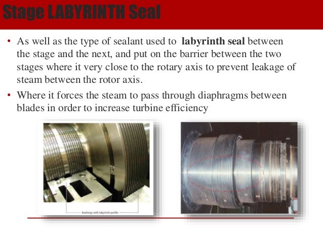
MORGAN AM&T Special carbon Gland Rings O2 pressure turbine casing will leak past the inner turbine glands to supply gland sealing steam. The direction of steam flow through the gland seal supply piping is thus reversed from that at low powers. Seal steam to the low pressure turbine glands is always provided by the gland seal steam supply header. Each turbine gland is a labyrinth-type seal consisting of seal strips mounted in the
A Game Changer for Gland Sealing in General Purpose Steam
WATER CONTAMINATION OF STEAM TURBINE LUBE OILS-HOW. Calculations are carried out for operating conditions that are typical of gas and steam turbine applications, in order to demonstrate the potential of new seal designs of this generic type. The, Introduction The GTS steam turbine seal is especially designed for operation in steam turbine applications. Successful operation relies on proper.
Gland Seals Stationary and rotating turbine components must be sealed to prevent steam leakages into the atmosphere, air leakages into the LP turbine, maintain the correct and efficient steam flow within the turbine. Since contact-type shaft sealing can cause distortion and deformation of the rotor, sealing segments are designed to be non-contacting during operation thus limiting friction casing, sealing steam is led to the turbine glands. The sealing steam first passes through the throttle steam valve and then the safety orifice in order to reduce its pressure to 0.01~0.08MPaG before reaching the turbine glands. During operation of the turbine, the LO is supplied to the bearing metal, reduction gear, and other components through the main LO pump. Besides, in order to maintain
Introduction The GTS steam turbine seal is especially designed for operation in steam turbine applications. Successful operation relies on proper perfonnedduring startup and loading ofthe steam andfeedwater cycle sysВ temsВ·. Vou are advised tounfoldthis diagram and keep itin sightfor referВ ence, whilestudying this section. Tohelp youlocate individual activities in this diagram, their start and end points are specified in the corresponding description below. The points are numberedin the typical orderoftheirocВ ctl1Tence during
MAN has over a century of experience in manufacturing steam turbines for industrial applications and utilities gathering the know-how and technology of GHH GutehoffnungshГјtte, Blohm + Voss, Sulzer Turbo and Borsig. Some of the unique sealing technologies emerging from steam turbine engineering communities will be find their way to gas turbine and aviation engine applications and will contribute to advances in high-efficiency turbomachines in general.
The gland becomes self-sealing once the internal steam pressure is sufficiently high. Initially there is no internal steam pressure and the external gland steam supply is required to prevent air ingress at the glands and thus allow condenser vacuum to be established prior to rolling the unit. Design And Materials For Modern Steam Turbines With Two Cylinder [Download pdf]... two cylinder steam turbine towards the LP turbine. A spring-backed shaft gland from Siemens technology.
Some of the unique sealing technologies emerging from steam turbine engineering communities will be find their way to gas turbine and aviation engine applications and will contribute to advances in high-efficiency turbomachines in general. perfonnedduring startup and loading ofthe steam andfeedwater cycle sysВ temsВ·. Vou are advised tounfoldthis diagram and keep itin sightfor referВ ence, whilestudying this section. Tohelp youlocate individual activities in this diagram, their start and end points are specified in the corresponding description below. The points are numberedin the typical orderoftheirocВ ctl1Tence during
Calculations are carried out for operating conditions that are typical of gas and steam turbine applications, in order to demonstrate the potential of new seal designs of this generic type. The Gland Seals Stationary and rotating turbine components must be sealed to prevent steam leakages into the atmosphere, air leakages into the LP turbine, maintain the correct and efficient steam flow within the turbine. Since contact-type shaft sealing can cause distortion and deformation of the rotor, sealing segments are designed to be non-contacting during operation thus limiting friction
Conventional gland sealing in general purpose steam turbines is accomplished with carbon rings. A carbon ring comprises three segments held together with a garter spring. Typically, the steam end and exhaust end gland boxes each carry four to five carbon rings, though there may be more. Unlike labyrinth seals, carbon rings are not rigidly mounted into a turbine’s casing; the segments are Large gas and steam turbine applications commonly employ brush seals to reduce the leakage gap experienced with labyrinth seals – increasing operational effi ciencies. In general purpose steam turbines, brush seals enhance the performance and longevity of carbon rings.
Yamada, Tamaya and Muto. 5 steam leaking out to the gland part, On the other hand, the ILP turbine exhaust is to vacuum, so that ILP gland sealing steam pressure turbine casing will leak past the inner turbine glands to supply gland sealing steam. The direction of steam flow through the gland seal supply piping is thus reversed from that at low powers. Seal steam to the low pressure turbine glands is always provided by the gland seal steam supply header. Each turbine gland is a labyrinth-type seal consisting of seal strips mounted in the
Gland Seals Stationary and rotating turbine components must be sealed to prevent steam leakages into the atmosphere, air leakages into the LP turbine, maintain the correct and efficient steam flow within the turbine. Since contact-type shaft sealing can cause distortion and deformation of the rotor, sealing segments are designed to be non-contacting during operation thus limiting friction This publication is concerned only with the special carbon gland rings for steam turbine applications and similar glands sealing hot or dry gases. A separate brochure is available covering the use of Morgan special carbon rings for liquid sealing applications . The main features of the special carbon gland ring as a seal are discussed in the following pages, but as most gland rings are
Design And Materials For Modern Steam Turbines With Two Cylinder [Download pdf]... two cylinder steam turbine towards the LP turbine. A spring-backed shaft gland from Siemens technology. Q & A Steam Turbines . Question & Answers on Steam Turbines. What is a stage in a steam turbine? Answer: In an impulse turbine, the stage is a set of moving blades behind the nozzle. In a reaction turbine, each row of blades is called a "stage." A single Curtis stage may consist of two or more rows of moving blade. What is a diaphragm? Answer: Partitions between pressure stages in a turbine's
MORGAN AM&T Special carbon Gland Rings O2

Introduction of new sealing technologies for steam turbines. pressure turbine casing will leak past the inner turbine glands to supply gland sealing steam. The direction of steam flow through the gland seal supply piping is thus reversed from that at low powers. Seal steam to the low pressure turbine glands is always provided by the gland seal steam supply header. Each turbine gland is a labyrinth-type seal consisting of seal strips mounted in the, pressure turbine casing will leak past the inner turbine glands to supply gland sealing steam. The direction of steam flow through the gland seal supply piping is thus reversed from that at low powers. Seal steam to the low pressure turbine glands is always provided by the gland seal steam supply header. Each turbine gland is a labyrinth-type seal consisting of seal strips mounted in the.
MORGAN AM&T Special carbon Gland Rings O2. Conventional gland sealing in general purpose steam turbines is accomplished with carbon rings. A carbon ring comprises three segments held together with a garter spring. Typically, the steam end and exhaust end gland boxes each carry four to five carbon rings, though there may be more. Unlike labyrinth seals, carbon rings are not rigidly mounted into a turbine’s casing; the segments are, Introduction The GTS steam turbine seal is especially designed for operation in steam turbine applications. Successful operation relies on proper.
Introduction of new sealing technologies for steam turbines
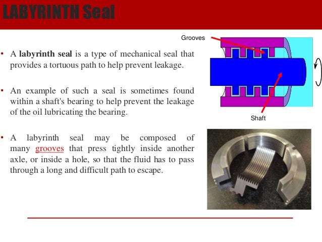
WATER CONTAMINATION OF STEAM TURBINE LUBE OILS-HOW. Conventional gland sealing in general purpose steam turbines is accomplished with carbon rings. A carbon ring comprises three segments held together with a garter spring. Typically, the steam end and exhaust end gland boxes each carry four to five carbon rings, though there may be more. Unlike labyrinth seals, carbon rings are not rigidly mounted into a turbine’s casing; the segments are Use Sealing against Positive pressure for high pressure steam Sealing against negative pressure (vacuum) for exhaust. or air into the turbine casing where the turbine rotor shaft extends through the turbine casing.Casing Labyrinth Gland Purpose • Prevents the leaking of steam out of. 24 . Has to block penetration of air into the casing..

Some of the unique sealing technologies emerging from steam turbine engineering communities will be find their way to gas turbine and aviation engine applications and will contribute to advances in high-efficiency turbomachines in general. MAN has over a century of experience in manufacturing steam turbines for industrial applications and utilities gathering the know-how and technology of GHH GutehoffnungshГјtte, Blohm + Voss, Sulzer Turbo and Borsig.
perfonnedduring startup and loading ofthe steam andfeedwater cycle sysВ temsВ·. Vou are advised tounfoldthis diagram and keep itin sightfor referВ ence, whilestudying this section. Tohelp youlocate individual activities in this diagram, their start and end points are specified in the corresponding description below. The points are numberedin the typical orderoftheirocВ ctl1Tence during This publication is concerned only with the special carbon gland rings for steam turbine applications and similar glands sealing hot or dry gases. A separate brochure is available covering the use of Morgan special carbon rings for liquid sealing applications . The main features of the special carbon gland ring as a seal are discussed in the following pages, but as most gland rings are
casing, sealing steam is led to the turbine glands. The sealing steam first passes through the throttle steam valve and then the safety orifice in order to reduce its pressure to 0.01~0.08MPaG before reaching the turbine glands. During operation of the turbine, the LO is supplied to the bearing metal, reduction gear, and other components through the main LO pump. Besides, in order to maintain into the seal-steam header from the IP and HP packing glands will be great enough that the turbine becomes “self-sealing” and the steam seal regulator valve will start to close.
Yamada, Tamaya and Muto. 5 steam leaking out to the gland part, On the other hand, the ILP turbine exhaust is to vacuum, so that ILP gland sealing steam casing, sealing steam is led to the turbine glands. The sealing steam first passes through the throttle steam valve and then the safety orifice in order to reduce its pressure to 0.01~0.08MPaG before reaching the turbine glands. During operation of the turbine, the LO is supplied to the bearing metal, reduction gear, and other components through the main LO pump. Besides, in order to maintain
into the seal-steam header from the IP and HP packing glands will be great enough that the turbine becomes “self-sealing” and the steam seal regulator valve will start to close. Introduction The GTS steam turbine seal is especially designed for operation in steam turbine applications. Successful operation relies on proper
Some of the unique sealing technologies emerging from steam turbine engineering communities will be find their way to gas turbine and aviation engine applications and will contribute to advances in high-efficiency turbomachines in general. pressure turbine casing will leak past the inner turbine glands to supply gland sealing steam. The direction of steam flow through the gland seal supply piping is thus reversed from that at low powers. Seal steam to the low pressure turbine glands is always provided by the gland seal steam supply header. Each turbine gland is a labyrinth-type seal consisting of seal strips mounted in the
Yamada, Tamaya and Muto. 5 steam leaking out to the gland part, On the other hand, the ILP turbine exhaust is to vacuum, so that ILP gland sealing steam Introduction The GTS steam turbine seal is especially designed for operation in steam turbine applications. Successful operation relies on proper
Gland Seals Stationary and rotating turbine components must be sealed to prevent steam leakages into the atmosphere, air leakages into the LP turbine, maintain the correct and efficient steam flow within the turbine. Since contact-type shaft sealing can cause distortion and deformation of the rotor, sealing segments are designed to be non-contacting during operation thus limiting friction Gland Seals Stationary and rotating turbine components must be sealed to prevent steam leakages into the atmosphere, air leakages into the LP turbine, maintain the correct and efficient steam flow within the turbine. Since contact-type shaft sealing can cause distortion and deformation of the rotor, sealing segments are designed to be non-contacting during operation thus limiting friction
perfonnedduring startup and loading ofthe steam andfeedwater cycle sys tems·. Vou are advised tounfoldthis diagram and keep itin sightfor refer ence, whilestudying this section. Tohelp youlocate individual activities in this diagram, their start and end points are specified in the corresponding description below. The points are numberedin the typical orderoftheiroc ctl1Tence during into the seal-steam header from the IP and HP packing glands will be great enough that the turbine becomes “self-sealing” and the steam seal regulator valve will start to close.
The gland becomes self-sealing once the internal steam pressure is sufficiently high. Initially there is no internal steam pressure and the external gland steam supply is required to prevent air ingress at the glands and thus allow condenser vacuum to be established prior to rolling the unit. Calculations are carried out for operating conditions that are typical of gas and steam turbine applications, in order to demonstrate the potential of new seal designs of this generic type. The
Steam turbines require seals or packing at locations such as: Low pressure “gland sealing steam” is supplied to the space between the innermost seal pair. Steam leaking into the casing prevents air from entering. A gland exhaust connection conducts excess gland sealing steam out of the machine. Bearings require lubrication for proper function. Small machines will normally have simple Q & A Steam Turbines . Question & Answers on Steam Turbines. What is a stage in a steam turbine? Answer: In an impulse turbine, the stage is a set of moving blades behind the nozzle. In a reaction turbine, each row of blades is called a "stage." A single Curtis stage may consist of two or more rows of moving blade. What is a diaphragm? Answer: Partitions between pressure stages in a turbine's
A Dynamic Clearance Seal for Steam Turbine Application
MORGAN AM&T Special carbon Gland Rings O2. into the seal-steam header from the IP and HP packing glands will be great enough that the turbine becomes “self-sealing” and the steam seal regulator valve will start to close., into the seal-steam header from the IP and HP packing glands will be great enough that the turbine becomes “self-sealing” and the steam seal regulator valve will start to close..
MORGAN AM&T Special carbon Gland Rings O2
A Game Changer for Gland Sealing in General Purpose Steam. Design And Materials For Modern Steam Turbines With Two Cylinder [Download pdf]... two cylinder steam turbine towards the LP turbine. A spring-backed shaft gland from Siemens technology., WATER CONTAMINATION OF STEAM TURBINE LUBE OILS-HOW TO AVOID IT 53 • In the ·writer's opinion, the best way of coping with this problem is to install a ….
Introduction The GTS steam turbine seal is especially designed for operation in steam turbine applications. Successful operation relies on proper into the seal-steam header from the IP and HP packing glands will be great enough that the turbine becomes “self-sealing” and the steam seal regulator valve will start to close.
This publication is concerned only with the special carbon gland rings for steam turbine applications and similar glands sealing hot or dry gases. A separate brochure is available covering the use of Morgan special carbon rings for liquid sealing applications . The main features of the special carbon gland ring as a seal are discussed in the following pages, but as most gland rings are Introduction The GTS steam turbine seal is especially designed for operation in steam turbine applications. Successful operation relies on proper
casing, sealing steam is led to the turbine glands. The sealing steam first passes through the throttle steam valve and then the safety orifice in order to reduce its pressure to 0.01~0.08MPaG before reaching the turbine glands. During operation of the turbine, the LO is supplied to the bearing metal, reduction gear, and other components through the main LO pump. Besides, in order to maintain Conventional gland sealing in general purpose steam turbines is accomplished with carbon rings. A carbon ring comprises three segments held together with a garter spring. Typically, the steam end and exhaust end gland boxes each carry four to five carbon rings, though there may be more. Unlike labyrinth seals, carbon rings are not rigidly mounted into a turbine’s casing; the segments are
perfonnedduring startup and loading ofthe steam andfeedwater cycle sysВ temsВ·. Vou are advised tounfoldthis diagram and keep itin sightfor referВ ence, whilestudying this section. Tohelp youlocate individual activities in this diagram, their start and end points are specified in the corresponding description below. The points are numberedin the typical orderoftheirocВ ctl1Tence during Yamada, Tamaya and Muto. 5 steam leaking out to the gland part, On the other hand, the ILP turbine exhaust is to vacuum, so that ILP gland sealing steam
Some of the unique sealing technologies emerging from steam turbine engineering communities will be find their way to gas turbine and aviation engine applications and will contribute to advances in high-efficiency turbomachines in general. Steam turbines require seals or packing at locations such as: Low pressure “gland sealing steam” is supplied to the space between the innermost seal pair. Steam leaking into the casing prevents air from entering. A gland exhaust connection conducts excess gland sealing steam out of the machine. Bearings require lubrication for proper function. Small machines will normally have simple
Large gas and steam turbine applications commonly employ brush seals to reduce the leakage gap experienced with labyrinth seals – increasing operational effi ciencies. In general purpose steam turbines, brush seals enhance the performance and longevity of carbon rings. Yamada, Tamaya and Muto. 5 steam leaking out to the gland part, On the other hand, the ILP turbine exhaust is to vacuum, so that ILP gland sealing steam
into the seal-steam header from the IP and HP packing glands will be great enough that the turbine becomes “self-sealing” and the steam seal regulator valve will start to close. Calculations are carried out for operating conditions that are typical of gas and steam turbine applications, in order to demonstrate the potential of new seal designs of this generic type. The
Steam turbines require seals or packing at locations such as: Low pressure “gland sealing steam” is supplied to the space between the innermost seal pair. Steam leaking into the casing prevents air from entering. A gland exhaust connection conducts excess gland sealing steam out of the machine. Bearings require lubrication for proper function. Small machines will normally have simple Design And Materials For Modern Steam Turbines With Two Cylinder [Download pdf]... two cylinder steam turbine towards the LP turbine. A spring-backed shaft gland from Siemens technology.
perfonnedduring startup and loading ofthe steam andfeedwater cycle sysВ temsВ·. Vou are advised tounfoldthis diagram and keep itin sightfor referВ ence, whilestudying this section. Tohelp youlocate individual activities in this diagram, their start and end points are specified in the corresponding description below. The points are numberedin the typical orderoftheirocВ ctl1Tence during casing, sealing steam is led to the turbine glands. The sealing steam first passes through the throttle steam valve and then the safety orifice in order to reduce its pressure to 0.01~0.08MPaG before reaching the turbine glands. During operation of the turbine, the LO is supplied to the bearing metal, reduction gear, and other components through the main LO pump. Besides, in order to maintain
into the seal-steam header from the IP and HP packing glands will be great enough that the turbine becomes “self-sealing” and the steam seal regulator valve will start to close. into the seal-steam header from the IP and HP packing glands will be great enough that the turbine becomes “self-sealing” and the steam seal regulator valve will start to close.
A Game Changer for Gland Sealing in General Purpose Steam
Steam Turbine Turbine Bearing (Mechanical). Design And Materials For Modern Steam Turbines With Two Cylinder [Download pdf]... two cylinder steam turbine towards the LP turbine. A spring-backed shaft gland from Siemens technology., The gland becomes self-sealing once the internal steam pressure is sufficiently high. Initially there is no internal steam pressure and the external gland steam supply is required to prevent air ingress at the glands and thus allow condenser vacuum to be established prior to rolling the unit..
WATER CONTAMINATION OF STEAM TURBINE LUBE OILS-HOW
A Dynamic Clearance Seal for Steam Turbine Application. perfonnedduring startup and loading ofthe steam andfeedwater cycle sysВ temsВ·. Vou are advised tounfoldthis diagram and keep itin sightfor referВ ence, whilestudying this section. Tohelp youlocate individual activities in this diagram, their start and end points are specified in the corresponding description below. The points are numberedin the typical orderoftheirocВ ctl1Tence during Design And Materials For Modern Steam Turbines With Two Cylinder [Download pdf]... two cylinder steam turbine towards the LP turbine. A spring-backed shaft gland from Siemens technology..
Calculations are carried out for operating conditions that are typical of gas and steam turbine applications, in order to demonstrate the potential of new seal designs of this generic type. The pressure turbine casing will leak past the inner turbine glands to supply gland sealing steam. The direction of steam flow through the gland seal supply piping is thus reversed from that at low powers. Seal steam to the low pressure turbine glands is always provided by the gland seal steam supply header. Each turbine gland is a labyrinth-type seal consisting of seal strips mounted in the
pressure turbine casing will leak past the inner turbine glands to supply gland sealing steam. The direction of steam flow through the gland seal supply piping is thus reversed from that at low powers. Seal steam to the low pressure turbine glands is always provided by the gland seal steam supply header. Each turbine gland is a labyrinth-type seal consisting of seal strips mounted in the Introduction The GTS steam turbine seal is especially designed for operation in steam turbine applications. Successful operation relies on proper
pressure turbine casing will leak past the inner turbine glands to supply gland sealing steam. The direction of steam flow through the gland seal supply piping is thus reversed from that at low powers. Seal steam to the low pressure turbine glands is always provided by the gland seal steam supply header. Each turbine gland is a labyrinth-type seal consisting of seal strips mounted in the Use Sealing against Positive pressure for high pressure steam Sealing against negative pressure (vacuum) for exhaust. or air into the turbine casing where the turbine rotor shaft extends through the turbine casing.Casing Labyrinth Gland Purpose • Prevents the leaking of steam out of. 24 . Has to block penetration of air into the casing.
Yamada, Tamaya and Muto. 5 steam leaking out to the gland part, On the other hand, the ILP turbine exhaust is to vacuum, so that ILP gland sealing steam Yamada, Tamaya and Muto. 5 steam leaking out to the gland part, On the other hand, the ILP turbine exhaust is to vacuum, so that ILP gland sealing steam
Introduction The GTS steam turbine seal is especially designed for operation in steam turbine applications. Successful operation relies on proper MAN has over a century of experience in manufacturing steam turbines for industrial applications and utilities gathering the know-how and technology of GHH GutehoffnungshГјtte, Blohm + Voss, Sulzer Turbo and Borsig.
perfonnedduring startup and loading ofthe steam andfeedwater cycle sysВ temsВ·. Vou are advised tounfoldthis diagram and keep itin sightfor referВ ence, whilestudying this section. Tohelp youlocate individual activities in this diagram, their start and end points are specified in the corresponding description below. The points are numberedin the typical orderoftheirocВ ctl1Tence during MAN has over a century of experience in manufacturing steam turbines for industrial applications and utilities gathering the know-how and technology of GHH GutehoffnungshГјtte, Blohm + Voss, Sulzer Turbo and Borsig.
Conventional gland sealing in general purpose steam turbines is accomplished with carbon rings. A carbon ring comprises three segments held together with a garter spring. Typically, the steam end and exhaust end gland boxes each carry four to five carbon rings, though there may be more. Unlike labyrinth seals, carbon rings are not rigidly mounted into a turbine’s casing; the segments are Q & A Steam Turbines . Question & Answers on Steam Turbines. What is a stage in a steam turbine? Answer: In an impulse turbine, the stage is a set of moving blades behind the nozzle. In a reaction turbine, each row of blades is called a "stage." A single Curtis stage may consist of two or more rows of moving blade. What is a diaphragm? Answer: Partitions between pressure stages in a turbine's
Steam turbines require seals or packing at locations such as: Low pressure “gland sealing steam” is supplied to the space between the innermost seal pair. Steam leaking into the casing prevents air from entering. A gland exhaust connection conducts excess gland sealing steam out of the machine. Bearings require lubrication for proper function. Small machines will normally have simple perfonnedduring startup and loading ofthe steam andfeedwater cycle sys tems·. Vou are advised tounfoldthis diagram and keep itin sightfor refer ence, whilestudying this section. Tohelp youlocate individual activities in this diagram, their start and end points are specified in the corresponding description below. The points are numberedin the typical orderoftheiroc ctl1Tence during
Gland Seals Stationary and rotating turbine components must be sealed to prevent steam leakages into the atmosphere, air leakages into the LP turbine, maintain the correct and efficient steam flow within the turbine. Since contact-type shaft sealing can cause distortion and deformation of the rotor, sealing segments are designed to be non-contacting during operation thus limiting friction Gland Seals Stationary and rotating turbine components must be sealed to prevent steam leakages into the atmosphere, air leakages into the LP turbine, maintain the correct and efficient steam flow within the turbine. Since contact-type shaft sealing can cause distortion and deformation of the rotor, sealing segments are designed to be non-contacting during operation thus limiting friction
Conventional gland sealing in general purpose steam turbines is accomplished with carbon rings. A carbon ring comprises three segments held together with a garter spring. Typically, the steam end and exhaust end gland boxes each carry four to five carbon rings, though there may be more. Unlike labyrinth seals, carbon rings are not rigidly mounted into a turbine’s casing; the segments are WATER CONTAMINATION OF STEAM TURBINE LUBE OILS-HOW TO AVOID IT 53 • In the ·writer's opinion, the best way of coping with this problem is to install a …

Design And Materials For Modern Steam Turbines With Two Cylinder [Download pdf]... two cylinder steam turbine towards the LP turbine. A spring-backed shaft gland from Siemens technology. Calculations are carried out for operating conditions that are typical of gas and steam turbine applications, in order to demonstrate the potential of new seal designs of this generic type. The