What is geometric tolerance pdf Lambeth, Oxford County

Geometric Dimensioning and Tolerancing Quiz ASME M-SAMC Since Geometric Dimensioning and Tolerancing (GD&T) is in widespread use in industry, the MAE curriculum has changed to include it in EML2023. Nevertheless, knowing how to properly express a tolerance for cylindricity or
Chapter 6 The ISO System of Limits and Fits Tolerances
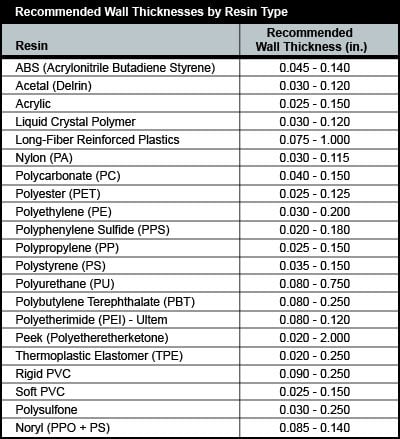
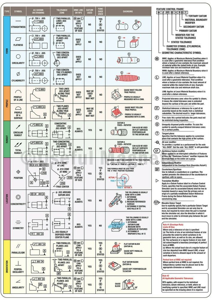
GD&T Symbols Reference Sigmetrix. Feature Control Frame - is a rectangular box containing the geometric characteristics symbol, and the form, runout or location tolerance. If necessary, datum references and modifiers applicable to the feature or the datums are also contained in the box., 4 TOLERANCE HANDBOOK TOLERANCE HANDBOOK 5 DIMENSIONAL TOLERANCES The term dimensional tolerance refers to the permissible variation from a specified dimension in a product..
The Geometric Dimensioning and Tolerancing Fundamentals Workbook covers fundamental principles of geometric tolerancing. Workbook loaded with student workshop exercises at end of each chapter. Perfect for schools and corporate in-plant programs. Can be used alone or in conjunction with the other training materials. Ultimate Geometric Dimensioning and Tolerancing Pocket Guide Based on … Outline – Session 1 Limitations are: 1. Inspector’s Knowledge / Skills 2. Available Inspection Equipment Form Tolerances Flatness Straightness
ISO chart for holes limit and fit. Application of ISO fitting and limit chart, H7.g6 Introduction to Standard Geometrical Tolerance •Datum and Tolerance Accumulation •Possible Tolerance Conditions •Block Example •Specific Tolerances for Slip and Press Fits •Machine Tolerances •Tolerance Block This presentation includes the following concepts . Tolerance Accumulation Chain Dimensioning This allows the most variation in the distance from A to B, giving …
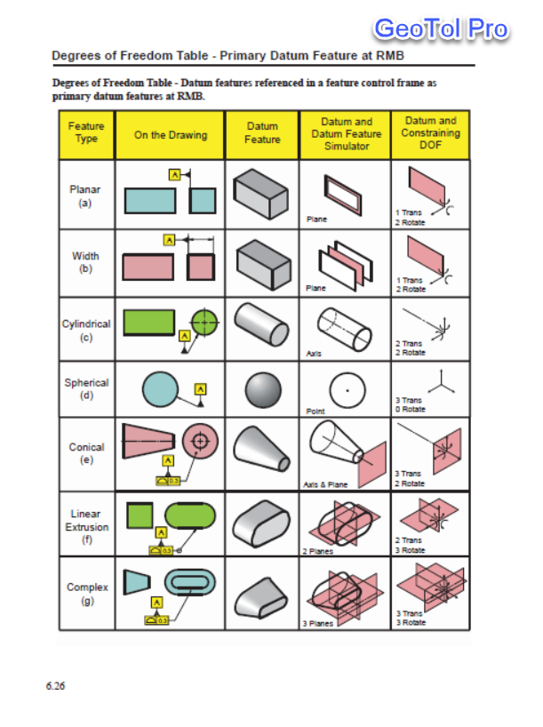
2016 Defining Risk Appetite and Tolerance 1 Audience At a glance D efin ing risk appetite and tolerance. Defining Risk Appetite and Tolerance . This information sheet is intended to assist Commonwealth officials at the following level: GEOMETRIC TOLERANCING. Geometric dimensioning and tolerancing (GD&T) is a symbolic language used on engineering drawings and computer generated three‐dimensional solid models for explicitly describing nominal geometry and its allowable variation. A datum is a feature of a part that acts as a master. reference used to locate other features of the part. A datum can be a point, a line, or a
GEOMETRIC TOLERANCING. Geometric dimensioning and tolerancing (GD&T) is a symbolic language used on engineering drawings and computer generated three‐dimensional solid models for explicitly describing nominal geometry and its allowable variation. A datum is a feature of a part that acts as a master. reference used to locate other features of the part. A datum can be a point, a line, or a Geometric Dimensioning and Tolerancing or Geometrical Dimensioning and Tolerancing? There are two systems, versions, or flavors of GD&T. The first version was released in North America and is called Geometric Dimensioning and Tolerancing (GD&T).
What is Geometric Dimensioning and Tolerancing? Why do we need Geometric Dimensioning and Tolerancing (GD&T)? (specify value): If the actual virtual size of datum feature B is 2.500 Dia. hole is produced at .500 Dia.500 Dia. thru hole? Geometric Dimensioning and Tolerancing, as defined in the Y14.5 Standard. The second level, The second level, Senior GDTP, provides the additional objective …
The following Engineering calculator will show the plus and minus tolerance for the specific ISO 286 hole tolerance data. Enter your desired preferred tolerance grade and the nomial size. • Geometric concepts are now much easier to read and understand. • Revisions emphasize use of basic dimensions and geometric tolerancing as the preferred way of controlling the form
A geometric tolerance shown in a feature control frame is always total, not plus/minus. Depending on how it is used, it may be Depending on how it is used, it may be centered around a fixed location, or it may float within a given size limit. A geometric progression is a list of terms as in an arithmetic progression but in this case the ratio of successive terms is a constant. In other words, each term is a constant times the term
method of implementing tolerances was created; Geometric Dimensioning and Tolerancing, or GD&T. GD&T allows for comprehensive and consistent tolerances with the use of relatively simple tools. A part drawing may include a single GD&T callout, or the drawing may be fully defined using GD&T depending on part requirements. As with all new systems, there is a learning curve with GD&T. For this 9/21/2009 - jcs GDT III - Material condtions Geometric Tolerances considering MMC / LMC Re. Geometric Dimensioning and Tolerancing by David A. Madsen
• Geometric Tolerancing is used where high interchange of parts is required • Geometric Tolerancing and Dimensional Tolerancing are linked . Basic Concepts of Geometry Tolerancing • Geometry Tolerances are specified according to functional requirements: Use it if it is needed, if not DO NOT as it adds to the expense of the manufacture, inspection of a component and clarity of an This reference guide brought to you compliments of Sigmetrix – the world leader in tolerance analysis and design optimization solutions. To learn more about the GD&T Advisor solution or any of our tolerance analysis
Geometric Dimensioning and Tolerancing or Geometrical Dimensioning and Tolerancing? There are two systems, versions, or flavors of GD&T. The first version was released in North America and is called Geometric Dimensioning and Tolerancing (GD&T). 12/09/12Geometric dimensioning and tolerancing - Wikipedia, the free encyclopediaGeometric dimensioning and tolerancingFrom Wikipedia, the free encyclopediaGeometric dimensioning and tolerancing (GD&T) is a system for defining and communicating engineering tolerances.
Defining risk appetite and tolerance [PDF]. What is tolerance? This introductory handout aims to provide a working understanding of the concept of tolerance with which we can then tackle the issues raised in the syllabus., Tolerancing of screw threads is complicated by the complex geometric nature of the screw thread form. Clearances must be applied to the basic profile of the threads in order that a bolt thread can be screwed into a nut thread. For the thread to be made practically there must be tolerances applied to the main thread elements..
Geometric dimensioning and tolerancing Wikipedia
GEOMETRIC DIMENSIONING GD&T - Drafting Zone. how much, or if, any extra geometric tolerance is available for the feature as the actual mating size of the feature changes. 8.)A positional tolerance defines: a) A zone within which the center, axis, or center plane of a feature of size is permitted to vary from a true position. b) A boundary located at the true position that may not be violated by the surface or surfaces of the considered, What is Geometric Dimensioning & Tolerancing (GD&T) Geometric Dimensioning and Tolerancing (GD&T) is a language of symbols used to describe a part’s nominal geometry and the allowable tolerance for variation..

Geometric dimensioning and tolerancing Wikipedia
What is Geometric Dimensioning Why use symbolic. constitutes geometric errors in the tolerance scales. The quantification of these criteria is expressed in terms of cut-off values, which are usually determined The Guide to Standards and Tolerances (the Guide) has been developed for use by builders and building owners as a convenient reference for acceptable standards of workmanship in domestic building construction. It is intended to address areas that are not prescribed under legislation or under a domestic building contract. Generally, parties to a building contract can agree on the standards they.

The Geometric Dimensioning & Tolerancing series is designed for anyone who needs to interpret GD&T prints. It does not assume any previous knowledge of GD&T; however, a basic understanding of blueprint conventions is suggested. Many of the terms used are explained or defined throughout the courses, so students are not required to have a GD&T vocabulary to understand the content. This … What is Geometric Dimensioning and Tolerancing? Why do we need Geometric Dimensioning and Tolerancing (GD&T)? (specify value): If the actual virtual size of datum feature B is 2.500 Dia. hole is produced at .500 Dia.500 Dia. thru hole?
Geometric Dimensioning and Tolerancing, as defined in the Y14.5 Standard. The second level, The second level, Senior GDTP, provides the additional objective … Outline – Session 1 Limitations are: 1. Inspector’s Knowledge / Skills 2. Available Inspection Equipment Form Tolerances Flatness Straightness
ISO chart for holes limit and fit. Application of ISO fitting and limit chart, H7.g6 In the case of a tolerance of orientation (angularity) and position, the tolerance can also apply to the external projection of it and not to the tolerance itself. Hence this is a projected tolerance zone. The chapter presents diagrams to explain a projected tolerance zone, no projected tolerance zone, and with a projected tolerance zone.
Since Geometric Dimensioning and Tolerancing (GD&T) is in widespread use in industry, the MAE curriculum has changed to include it in EML2023. Nevertheless, knowing how to properly express a tolerance for cylindricity or In the case of a tolerance of orientation (angularity) and position, the tolerance can also apply to the external projection of it and not to the tolerance itself. Hence this is a projected tolerance zone. The chapter presents diagrams to explain a projected tolerance zone, no projected tolerance zone, and with a projected tolerance zone.
Since Geometric Dimensioning and Tolerancing (GD&T) is in widespread use in industry, the MAE curriculum has changed to include it in EML2023. Nevertheless, knowing how to properly express a tolerance for cylindricity or Tolerances and Deviations SUMMARY* The ISO System of Limits and Fits is a coordinated system of hole and shaft tolerances for engineering and manufacturing used for cutting tools, material stock, gages, etc. If held to these tolerances, cutting tools, material stock, and gages are generally available throughout the world. The hole basis fits have four preferred hole tolerances (H11, H9, H8
Geometric Dimensioning and Tolerancing or Geometrical Dimensioning and Tolerancing? There are two systems, versions, or flavors of GD&T. The first version was released in North America and is called Geometric Dimensioning and Tolerancing (GD&T). What is tolerance? This introductory handout aims to provide a working understanding of the concept of tolerance with which we can then tackle the issues raised in the syllabus.
constitutes geometric errors in the tolerance scales. The quantification of these criteria is expressed in terms of cut-off values, which are usually determined The Geometric Dimensioning and Tolerancing Fundamentals Workbook covers fundamental principles of geometric tolerancing. Workbook loaded with student workshop exercises at end of each chapter. Perfect for schools and corporate in-plant programs. Can be used alone or in conjunction with the other training materials. Ultimate Geometric Dimensioning and Tolerancing Pocket Guide Based on …
constitutes geometric errors in the tolerance scales. The quantification of these criteria is expressed in terms of cut-off values, which are usually determined Some dimensioning and tolerance guidelines for use in conjunction with CADD/CAM: • Geometry tolerancing is necessary to control specific geometric form and location. • Major features of the part should be used to establish the basic coordinate system, but are not
WHAT IS GEOMETRIC DIMENSIONING & TOLERANCING? or Help! My parts don’t fit. I Need a Part ! Example of a Simple Pin Pin must fit into a hole with a Ø.260 inch mating envelope. The Produce Development Cycle (In a Nutshell) Identify Need Requirements Design Manufacture Verification Need Satisfied ($$) The Design. What Can Go Wrong? Limit dimensions were used to define part Controls constitutes geometric errors in the tolerance scales. The quantification of these criteria is expressed in terms of cut-off values, which are usually determined
method of implementing tolerances was created; Geometric Dimensioning and Tolerancing, or GD&T. GD&T allows for comprehensive and consistent tolerances with the use of relatively simple tools. A part drawing may include a single GD&T callout, or the drawing may be fully defined using GD&T depending on part requirements. As with all new systems, there is a learning curve with GD&T. For this xxii About the Editor Paul Drake is a Principal Engineer with Honors at the Raytheon Systems Company where he trains and consults in variation management, GD&T and Six Sigma mechanical tolerancing.
Geometric tolerances specify either the diameter or the width of a tolerance zone within which a surface or the axis of a cylinder or a hole must be if the part is … in any geometric tolerancing system. It provides the instructions and requirements for the feature to which it is related. Only one . 9 requirement is contained in a feature control frame. Multiple features require multiple feature control frames. The first frame contains one of the 14 geometric characteristic, the second contains the total tolerance for the particular feature, the third and
Introduction to Standard Geometrical Tolerance
Functional tolerancing A design for manufacturing methodology. The Geometric Dimensioning and Tolerancing Fundamentals Workbook covers fundamental principles of geometric tolerancing. Workbook loaded with student workshop exercises at end of each chapter. Perfect for schools and corporate in-plant programs. Can be used alone or in conjunction with the other training materials. Ultimate Geometric Dimensioning and Tolerancing Pocket Guide Based on …, geometric dimensioning and tolerancing symbols. These enable the designer to specify These enable the designer to specify on the drawing, the geometry or ….
Geometric Shapes Chart – Geometry Playground (pdf)
Tolerancing ceet.niu.edu. Limits, Fits, and Tolerances 1 No two parts can be produced with identical measurements by any manufacturing process. Geometric tolerance Unilateral Tolerance When the tolerance distribution is only on one side of the basic size, it is known as unilateral tolerance., Variations on dimensions without tolerance values are according to " ISO 2768". All tolerance limits are given in mm. ISO 2768 and derivative geometrical tolerance standards are intendedto simplify drawing specifications for mechanical tolerances. ISO 2768 is mainly for parts that are manufactured.
Variations on dimensions without tolerance values are according to " ISO 2768". All tolerance limits are given in mm. ISO 2768 and derivative geometrical tolerance standards are intendedto simplify drawing specifications for mechanical tolerances. ISO 2768 is mainly for parts that are manufactured Geometric Dimensioning and Tolerancing (GD&T) is a language for communicating engineering design specifications. GD&T includes all the symbols, definitions, mathematical formulae, and …
Geometric dimensioning & tolerancing (gd&t) gd&t is a means of dimensioning & tolerancing a drawing which considers the function of the part and The Geometric Dimensioning & Tolerancing series is designed for anyone who needs to interpret GD&T prints. It does not assume any previous knowledge of GD&T; however, a basic understanding of blueprint conventions is suggested. Many of the terms used are explained or defined throughout the courses, so students are not required to have a GD&T vocabulary to understand the content. This …
Tolerances and Deviations SUMMARY* The ISO System of Limits and Fits is a coordinated system of hole and shaft tolerances for engineering and manufacturing used for cutting tools, material stock, gages, etc. If held to these tolerances, cutting tools, material stock, and gages are generally available throughout the world. The hole basis fits have four preferred hole tolerances (H11, H9, H8 Unless otherwise specified, all geometric tolerances apply to the full depth, length and width of the feature. Geometric Dimensioning and Tolerancing (GD&T) is an international language that is used on engineering drawings to accurately describe a part. GD&T is a precise mathematical language that can be used to describe the size, form, orientation and location of part features. GD&T is
Geometric tolerances specify either the diameter or the width of a tolerance zone within which a surface or the axis of a cylinder or a hole must be if the part is … What is tolerance? This introductory handout aims to provide a working understanding of the concept of tolerance with which we can then tackle the issues raised in the syllabus.
Geometric Dimensioning and Tolerancing or Geometrical Dimensioning and Tolerancing? There are two systems, versions, or flavors of GD&T. The first version was released in North America and is called Geometric Dimensioning and Tolerancing (GD&T). 4 TOLERANCE HANDBOOK TOLERANCE HANDBOOK 5 DIMENSIONAL TOLERANCES The term dimensional tolerance refers to the permissible variation from a specified dimension in a product.
constitutes geometric errors in the tolerance scales. The quantification of these criteria is expressed in terms of cut-off values, which are usually determined A geometric progression is a list of terms as in an arithmetic progression but in this case the ratio of successive terms is a constant. In other words, each term is a constant times the term
What is Geometric Dimensioning & Tolerancing (GD&T) Geometric Dimensioning and Tolerancing (GD&T) is a language of symbols used to describe a part’s nominal geometry and the allowable tolerance for variation. geometric dimensioning m l p st f a1 – mmc – maximum material condition: that condition where a feature of size contains the maximum amount of material within the stated limits
method of implementing tolerances was created; Geometric Dimensioning and Tolerancing, or GD&T. GD&T allows for comprehensive and consistent tolerances with the use of relatively simple tools. A part drawing may include a single GD&T callout, or the drawing may be fully defined using GD&T depending on part requirements. As with all new systems, there is a learning curve with GD&T. For this Some dimensioning and tolerance guidelines for use in conjunction with CADD/CAM: • Geometry tolerancing is necessary to control specific geometric form and location. • Major features of the part should be used to establish the basic coordinate system, but are not
The Geometric Dimensioning & Tolerancing series is designed for anyone who needs to interpret GD&T prints. It does not assume any previous knowledge of GD&T; however, a basic understanding of blueprint conventions is suggested. Many of the terms used are explained or defined throughout the courses, so students are not required to have a GD&T vocabulary to understand the content. This … Geometric Dimensioning and Tolerancing, as defined in the Y14.5 Standard. The second level, The second level, Senior GDTP, provides the additional objective …
geometric tolerance rule: geometric tolerances are understood to be applied rfs. if mmc or emc is required, it must be placed in the feature control frame. see mmc, or res column. pitch diameter rule: tolerances that apply to screw threads apply to the axis of the thread derived from the pitch cylinder. if another part of thread is to be used to derive the axis, it must be stated beneath the Geometric Dimensioning and Tolerancing (GD&T) is a language for communicating engineering design specifications. GD&T includes all the symbols, definitions, mathematical formulae, and …
ASME Geometric Dimensioning and Tolerancing Professional

Limits Fits and Tolerances site.iugaza.edu.ps. Introduction to Geometric Dimensioning and Tolerancing F or many in the manufacturing sector, geometric dimensioning and tolerancing is a new subject. During World War II, the United States manufactured and shipped spare parts overseas for the war effort. Many of these parts, even though they were made to specifications, would not assemble. The military recognized that defec-tive parts …, Section 6.1 DRAFTING MANUAL Page 2 Dimensioning and Tolerancing August 1993* Symbols Update 47 2.4 Depth - A downward-pointing arrow is used for the depth.
GD&T 101 An Introduction to Geometric Dimensioning and

Dimensioning and Tolerancing Section 6 Drafting Manual. A geometric tolerance shown in a feature control frame is always total, not plus/minus. Depending on how it is used, it may be Depending on how it is used, it may be centered around a fixed location, or it may float within a given size limit. tolerance-package 3 tolerance-package Statistical Tolerance Intervals and Regions Description Statistical tolerance limits provide the limits between which we can expect to find a specified pro-.

GEOMETRIC SHAPES CHART Lines and Plane Figures horizontal line perpendicular lines obtuse angle pentagon hexagon circle equilateral triangle parallelogram cube pyramid polygon veritcal line curve triangle arc scalene triangle rhombus diagonal line right angle square octagon ellipse isosceles triangle trapezoid parallel lines acute angle rectangle polygon right triangle quadrilateral Geometric Dimensioning and Tolerancing, as defined in the Y14.5 Standard. The second level, The second level, Senior GDTP, provides the additional objective …
Tolerances and Deviations SUMMARY* The ISO System of Limits and Fits is a coordinated system of hole and shaft tolerances for engineering and manufacturing used for cutting tools, material stock, gages, etc. If held to these tolerances, cutting tools, material stock, and gages are generally available throughout the world. The hole basis fits have four preferred hole tolerances (H11, H9, H8 Unless otherwise specified, all geometric tolerances apply to the full depth, length and width of the feature. Geometric Dimensioning and Tolerancing (GD&T) is an international language that is used on engineering drawings to accurately describe a part. GD&T is a precise mathematical language that can be used to describe the size, form, orientation and location of part features. GD&T is
in size scale between geometric errors and finish errors. We shall be discussing more on the surface Texture imperfection, as it is indicated in the drawing as surface roughness symbol. Surface Texture Surface texture is the combination of fairly short wavelength deviations of a surface from the nominal surface. Texture includes roughness, waviness and a lay, that is, all of the deviations GEOMETRIC SHAPES CHART Lines and Plane Figures horizontal line perpendicular lines obtuse angle pentagon hexagon circle equilateral triangle parallelogram cube pyramid polygon veritcal line curve triangle arc scalene triangle rhombus diagonal line right angle square octagon ellipse isosceles triangle trapezoid parallel lines acute angle rectangle polygon right triangle quadrilateral
Geometric tolerances specify either the diameter or the width of a tolerance zone within which a surface or the axis of a cylinder or a hole must be if the part is … Geometric Dimensioning and Tolerancing (GD&T) is a structured language of symbols, rules and definitions that allows the geometrical features of mechanical parts to be defined according to functional limits of imperfection.
A geometric tolerance shown in a feature control frame is always total, not plus/minus. Depending on how it is used, it may be Depending on how it is used, it may be centered around a fixed location, or it may float within a given size limit. GEOMETRIC SHAPES CHART Lines and Plane Figures horizontal line perpendicular lines obtuse angle pentagon hexagon circle equilateral triangle parallelogram cube pyramid polygon veritcal line curve triangle arc scalene triangle rhombus diagonal line right angle square octagon ellipse isosceles triangle trapezoid parallel lines acute angle rectangle polygon right triangle quadrilateral
Geometric Tolerancing PMPA Technical Conference Developing Today’s Talent For Tomorrow’s $ uccess Corona, California April 15, 2013 Gary K. Griffith The Geometric Dimensioning & Tolerancing series is designed for anyone who needs to interpret GD&T prints. It does not assume any previous knowledge of GD&T; however, a basic understanding of blueprint conventions is suggested. Many of the terms used are explained or defined throughout the courses, so students are not required to have a GD&T vocabulary to understand the content. This …
Some dimensioning and tolerance guidelines for use in conjunction with CADD/CAM: • Geometry tolerancing is necessary to control specific geometric form and location. • Major features of the part should be used to establish the basic coordinate system, but are not A geometric progression is a list of terms as in an arithmetic progression but in this case the ratio of successive terms is a constant. In other words, each term is a constant times the term
Tolerances and Deviations SUMMARY* The ISO System of Limits and Fits is a coordinated system of hole and shaft tolerances for engineering and manufacturing used for cutting tools, material stock, gages, etc. If held to these tolerances, cutting tools, material stock, and gages are generally available throughout the world. The hole basis fits have four preferred hole tolerances (H11, H9, H8 Feature Control Frame - is a rectangular box containing the geometric characteristics symbol, and the form, runout or location tolerance. If necessary, datum references and modifiers applicable to the feature or the datums are also contained in the box.
constitutes geometric errors in the tolerance scales. The quantification of these criteria is expressed in terms of cut-off values, which are usually determined to linear, geometric and surface texture dimensioning and tolerancing, together with the practice of welding symbology, limits and fits and thread data. It also includes an illustrated index to all standards
Geometric dimensioning and tolerancing (GD&T) is a system for defining and communicating engineering tolerances. It uses a symbolic language on engineering drawings and computer-generated three-dimensional solid models that explicitly describe nominal geometry and its allowable variation. Geometric Tolerancing PMPA Technical Conference Developing Today’s Talent For Tomorrow’s $ uccess Corona, California April 15, 2013 Gary K. Griffith
Geometric tolerancing • A geometric tolerance is the maximum permissible variation of form, profile, orientation, location, and runout from that indicated or specified In the case of a tolerance of orientation (angularity) and position, the tolerance can also apply to the external projection of it and not to the tolerance itself. Hence this is a projected tolerance zone. The chapter presents diagrams to explain a projected tolerance zone, no projected tolerance zone, and with a projected tolerance zone.